Structural analysis of a bike frame using multi-scenario design evaluation
This report includes several studies that highlight the stresses effects and optimize the design of a customized bicycle frame using (Solidworks) computer-aided design software and its FEM analysis package.
The research includes two types of static stress analysis methods. The first is beam treated frame with two-dimensional mech elements, which is the simplest, and the second is soled body and surfaces treated with three-dimensional mixed mesh, which is more accurate.
Multi scenarios have been applied to represent the static loads that may be applied by the rider to investigate which case has the highest impact on the stress concentration region, and base on it, the frequency and dynamic analyses have been applied to study the first 10 mode shapes and its relation with the natural frequency the result of those several studies has been discussed at the end of each section.
Based on the investigated results, generative modelling design has been applied to some critical components in the frame which have the highest weight in order to try to reduce its weight with an acceptable factor of safety. In general, bicycle frames have to bear a variety of loads, and it is needed to ensure the frame can withstand (static, dynamic loads to move and fatigue strength).
report studies bicycle frame structure with a purpose to avoid the problem regarding loads on the structure and to ensure the structure is safe when multiple loads are applied to it.
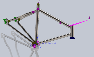
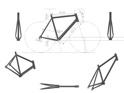
Simplify model (Treated as beams)
There are several ways to treat your model in FEM software and FEM solvers. The first model will be discussed as a beam connects with joints if we want to redesign and reanalyze, how quickly can we reconfigure the mesh, control the mesh and rerun again. It can get complicated with 3D meshing. In particular, this can slow down the turnaround of concept designs, and it might well be that a simpler approach to idealization can help here, if we want to redesign and reanalyze, how quickly can we reconfigure the mesh, control the mesh and rerun again. It can get complicated with 3D meshing. In particular, this can slow down the turnaround of concept designs, and it might well be that a simpler approach to idealization can help here.
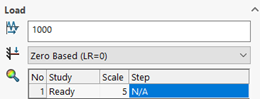
Loads
Mesh information
| Total Nodes | 45959 |
| Total Elements | 26328 |
Study Results
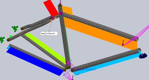
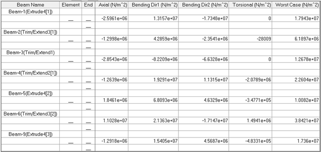
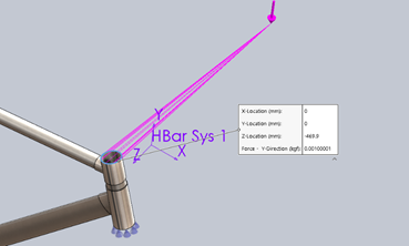
maximum axial force value equal 403.5N
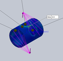
In conclusion the simplified study show that the maximum stress will be located at the BTM bracket with value of 89.9MPa with factor of safety of 4.893 which is safe for the current scenario and give us an indication about the forces and stresses. The shear generated in the beams is very low in al axis which is also good results and make us turn our attention to the other factors to be taken in consideration.
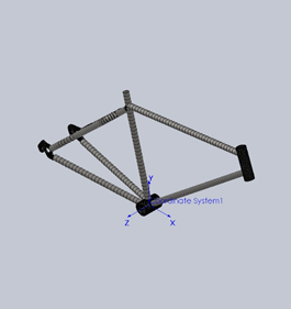
Accurate model (treated as solids and surfaces)
Fixtures
- Restriant
 Elastic connector
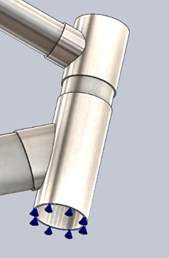
Loads
Part Rider Weight
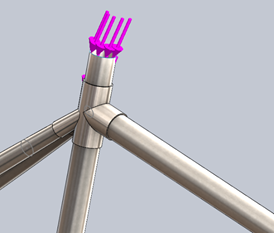 Part Rider Weight-2
Part Rider Weight-3
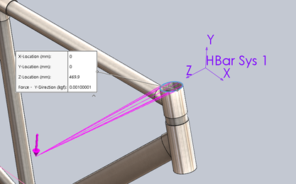
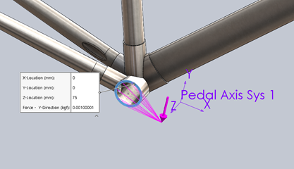
Pedal Force
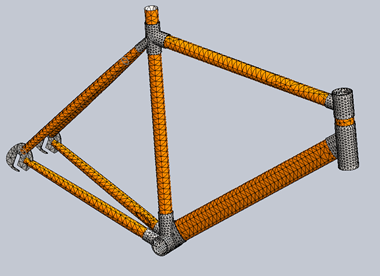
Mesh information
| Mesh type | Mixed Mesh |
| Mesher Used: | Standard mesh |
| Automatic Transition: | Off |
| Include Mesh Auto Loops: | Off |
| Jacobian points | 4 Points |
| Jacobian check for shell | Off |
| Element Size | 13.4771 mm |
| Tolerance | 0.673853 mm |
| Mesh Quality Plot | High |
| Total Nodes | 27863 |
| Total Elements | 13471 |
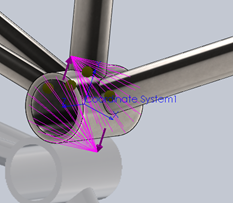
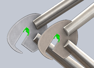
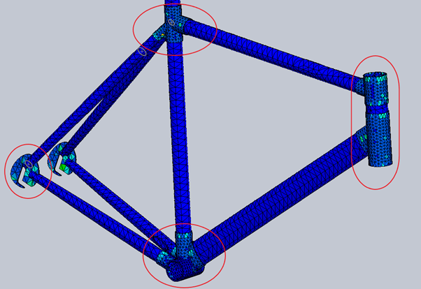
Mech control has been applied at the sharp edge point where high aspect ratio and Jacobians quality was low with element size of .6.737mm the highest aspect ratio found to be 39 in just element which is acceptable.
Dead loads study Results
Stress results
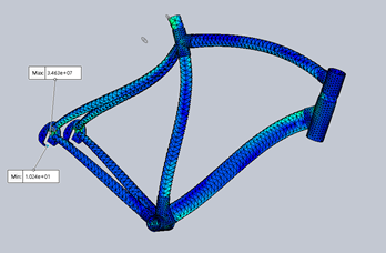
With deformation scale of 411 its noticed that where is the stress concentration regions.
The maximum stress found to be 34.36MPa and the minimum 1.024Pa lower in the dead region, the results gone as expected but there is some regions lower the seat and at the back axical assembly place It should be given some attention.the factor of safety on these regions is not that bad at all as shown below.
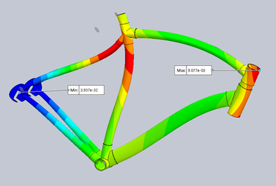
Displacement results
With scale of 411 the deformation is clearly shown, the maximum 0.23mm at the head top which is very good and does not bad for a material have such ductility as alloy steel.
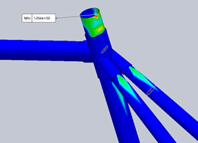
Factor of safety
It found that there is a minimum von mises factor of safety of 1.854 lower the seat which is the place mentioned before so this place can be reinforced to have higher factor of safety.
Part2: Active load(Cruising)
Stress results
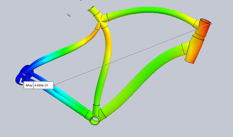
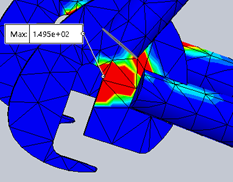
With deformation scale of 411 its noticed that where is the stress concentration regions the maximum stress found to be 73.81.36MPa, which is more than the double of the first study
\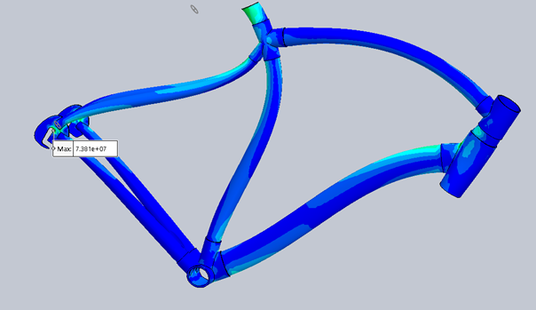
Displacement results
With scale of 411 the deformation is clearly shown, the maximum 0.4658mm at the head top which is exactly the double of the first study and does not bad for a material have such ductility as alloy steel.
Fatigue analysis of bike frame (Constant Amplitude)
In the case of bike frame its known that the bike pedal and other component have a cyclic motion with a variety of the loads That makes studying this topic so important to investigate the allowable fatigue stress and know the percent of damage after certain number of cycle, the study shows a fatigue analysis depends on each static load scenario that mentioned before in order to know which of these load have the highest impact on the frame on the long period.
Constant Amplitude Fatigue Analysis based on cursing loads
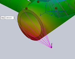
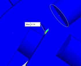
Damage percent
It found that the maximum percentage damage after 1000cycle is 11.4% in stress concentration region
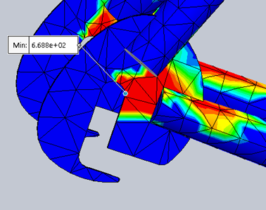
Loading factor
The loading factor found to be 4.129 which is good and larger than the failure loading factor with 412%
Constant amplitude fatigue analysis based on standing loads
By scaling up the loads 5 times and study the deformation after 1000 cycle the percentage of damage and life time for each element in the mesh has been estimated with zero type load assumption.
Damage percent
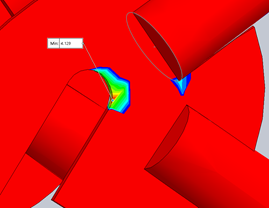
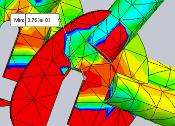
Loading factor
The loading factor found to be 0.8761 which is indicates that the failure could occurs in this region.
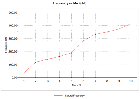
Frequency study
Natural frequencies and mode shapes will be described for the first 5 modes of the frame body.
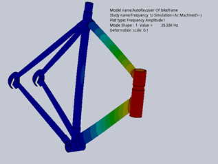
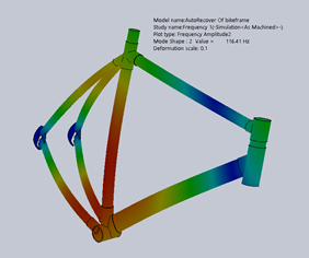
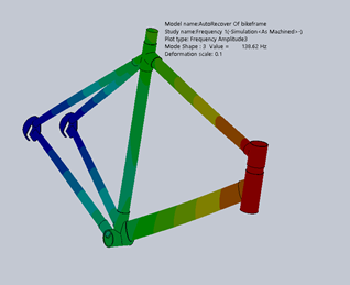
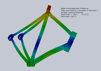

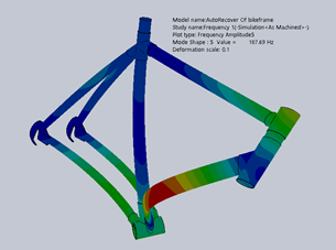
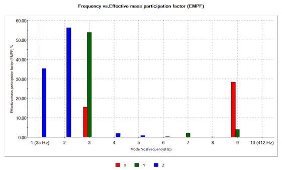
The figure below shoes the type of effective mass participate in each mode. The study of the effective mass is very important to improve the mass distribution in the frame in the next step in performance improving .the figure clearly shows that at the first two modes the mass effect on the Z axis ,at third mode the effective mass dominant on the y axis and have some effect on the x axis, in rest modes until 8 the effective mass have low factor values.
Conclusion
After applying multi scenarios and several methods to determine the allowable stresses, its shown that the maximum stress and damage related to the fatigue analysis, and the point of interest in the design parameters is to prevent any failure occurs due to the cyclic loads applied to the frame, the standing scenario have the most significant influence on the stress concentration regions. The study need to be completed to apply real time dynamic scenario to the frame, to take the results nearest to the reality and more accurate.